Time Interleave
Reference document
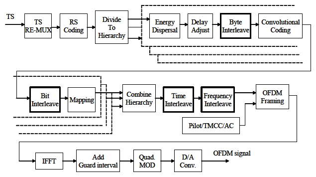
Figure 3-4 Functional block diagram of ISDB-T
Error correction system,generally, shows best performance against random error such as thermal noise, but not work well against burst error (concatenated error).
Therefore, technology for randomization of error is adopted with error correction system, this technology is called “Interleave” technology.
For an example, show at forward page the functional block diagram of ISDB-T in Figure 3-4.
As shown in Figure, ISDB-T has 4 kinds of Interleave. These are;
(1) Byte interleave, (2) Bit interleave, (3) Time interleave, (4) Frequency interleave, Effect of these interleave function is described in Figure 3-5.
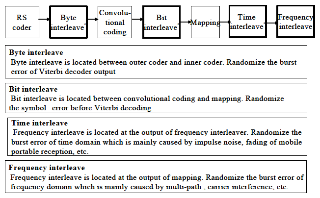
Figure 3-5 position of interleave circuits and these effect
As shown in figure, “Time Interleave” is quite effective to improve both robustness against impulse noise and performance for mobile/portable reception.
Impulse noise is dominant degradation factor in urban area, which caused from car engine, switching of electric equipment, called “manmade noise”.
ISDB-T only has the function of “Time Interleave”. Both DVB-T and ATSC do not have this function.
As a result, ISDB-T is significantly superior than other 2 systems, ATSC and DVB-T in reception performance of urban area and mobile/ portable reception performance.
As an example, Figure 3-6 shows the reception performance under impulse noise condition
As shown in figure, over 150 us pulse width, ISDB-T is about 7dB better than other 2 system for reception performance.
7dB improvement means 1/5 less power of transmitter!
That is, if ATSC and DVB-T require 1 kW power of transmitter, ISDB-T require only 200W for same coverage!

Figure 3-6 Reception performance under Impulse noise condition (3 DTTB systems)